- SCOPE SETUP MANUAL
![[en]](../bfta-manuals-updated/en.png "[en]") English
English![[es]](../bfta-manuals-updated/es.png "[es]") Español / Spanish
Español / Spanish![[hr]](../bfta-manuals-updated/hr.png "[hr]") Hrvatski / Croatian
Hrvatski / Croatian![[hu]](../bfta-manuals-updated/hu.png "[hu]") Magyar / Hungarian
Magyar / Hungarian![[it]](../bfta-manuals-updated/it.png "[it]") Italiano / Italian
Italiano / Italian![[lt]](../bfta-manuals-updated/lt.png "[lt]") Lietuviškai / Lithuanian
Lietuviškai / Lithuanian![[rs]](../bfta-manuals-updated/rs.png "[rs]") Srpski / Serbian
Srpski / Serbian![[ru]](../bfta-manuals-updated/ru.png "[ru]") Русский / Russian
Русский / Russian- TECHNICAL SKILLS MANUAL
![[bg]](../bfta-manuals-updated/bg.png "[bg]") Български / Bulgarian
Български / Bulgarian- English
![[gr]](../bfta-manuals-updated/gr.png "[gr]") Ελληνικά / Greek
Ελληνικά / Greek- Hrvatski / Croatian
- Magyar / Hungarian
- Italiano / Italian
![[sk]](../bfta-manuals-updated/sk.png "[sk]") Slovenský / Slovakian
Slovenský / Slovakian- Русский / Russian
SEND E-MAIL
BFTA Scope Setup Manual - Updated by Maestro © Written by Wayne K. Hudson, 2002. © This document is copyright protected by the BFTA and András Fekete-Móró. Further translations are in progress by fellow shooters:
Contents 1. Introduction 3. Scope Mounting 4. Establishing the Trajectory 5. Rangefinding by Parallax Correction 6. Ballistics Explained 7. Trajectory Compensation by Holdover 1. Introduction The aim of this manual is not to teach a person how to shoot Field Target or how to shoot an air rifle in general. Before using this manual it is necessary to have been instructed on all aspects of air rifle handling and shooting, and for a basic level of understanding and proficiency to be present. This manual therefore assumes that the shooter is able to shoot to a basic standard, is able to shoot consistent groups on paper, and is ready to set up his gun/scope to the best available method, in order to accurately shoot at all ranges between 8 and 55 yards. It also presumes that the shooter owns a .177 calibre air rifle and a parallax-correcting scope. Although most of the instruction within relates to dialling, target-turret scopes, users of non-dialling scopes, and multi-aimpoint reticules are catered for in chapter seven. This manual is not meant to replace sensible advice given at club instructor level. Rather, it is meant to be a companion guide during the sometimes-difficult process of helping a relative novice to set up what can be a very complicated and expensive set of equipment. Armed with this manual, the instructor and novice shooter should be able to reduce the setting up period from a matter of weeks to a matter of days. It is the hope of the author that this manual will enable a relative novice to do so in a straightforward, systematic way. Wayne K. Hudson 2. Rifle Preparation It is important that the rifle is capable of doing certain functions: All Field Target shooting in the U.K. is done with rifles conforming to the statutory limit of under 12 ft-lb muzzle energy. Before commencing any further rifle set-up it is vital that you check the muzzle energy / velocity using a chronograph with the pellets you intend using. If the M.E. is too high then the rifle must be detuned. If the M.E. is too low then it may be advantageous to uprate the power to something nearer 11.5 ft-lb. Running at a muzzle energy of greater than 11.5 ft-lb is risky in terms of the law and is of dubious advantage anyway. To calculate the power of an airgun you need to use a chronograph to measure the speed of the pellet (in feet per second) when fired, and you need to know the weight of the pellet in grains. Once you have that information you perform the following calculation which gives you the result in foot pounds force (ft-lb): The trigger of each type of rifle is different so you will have to consult your owner's manual for details of how to adjust it. In Field Target, triggers tend to be set lighter than for hunting guns, but it is imperative that your trigger is not set so light that the rifle discharges on its own when cocked. It is also important that the trigger blade itself is correctly aligned and for the 'reach' from butt-pad to trigger to be correct. If the trigger is a multi-adjustable unit, the reach can be altered from there. For further details on triggers consult the BFTA Technical Skills Manual. With the rifle shouldered the trigger hand should find the pistol grip and trigger in a smooth motion without bunching or over-reaching. The trigger blade should sit on the pad of the index finger just after the final finger joint. If the trigger is not adjustable and the reach is too short, then extra butt-pad spacers can be inserted, or conversely, removed. If there are no spacers to remove then some slight woodworking may be required to remove material from the buttstock. As a rule of thumb, if you hold the grip comfortably, the butt pad has to reach the elbow bend without pushing it too firmly. In terms of pellet selection/accuracy, this manual assumes that the shooter already knows what is accurate in the rifle as he/she will have been shooting the rifle already, but without going through the full set-up procedure. Up to now you may have found a tendency to keep your non-aiming eye closed when shooting. However, it is very advantageous to learn to shoot with both eyes open. Rangefinding, as discussed later, can become difficult unless both eyes are completely relaxed. When using a gun/scope-mounted spirit level, it is difficult to check to see if the gun is level unless the non-aiming eye is free to monitor the level. Also, having both eyes open allows the shooter to better monitor the surroundings for wind effects. It is a technique that does not come naturally and has to be learned, but pays dividends when mastered. Once all the above has been completed, it is time to mount, (or remount) the scope. 3. Scope Mounting 3.1. Mount Height and Cheekpiece fit Getting the right height mounts can be a costly business. Getting it right means comfort and more targets hit. Getting it wrong means discomfort, frustration and fewer targets hit. The main factor in choosing a set of mounts (after the correct diameter) is the clearance between the front-end of the scope and the barrel. For a scope with an adjustable front end, mounting it too close to the barrel may cause it to touch, and even deflect the barrel, at the end of the scope's adjustment. The other factor is head alignment. If your scope is mounted too low you may find that you have to 'cram' your head onto the cheek piece or crank your head at an extreme angle in order to see the image. Conversely, if your scope is mounted too high, you may find yourself 'hovering' over the cheek piece, without your head touching the stock. In both cases this will induce unsteadiness as you fight to acquire a sight picture. Stocks with adjustable cheek pieces eliminate this problem, because as long as the objective bell is clear of the barrel the scope can be mounted at any height the shooter chooses*, ensuring optimum head position for maximum comfort. Usually it is the most vertical head position that is best, but this varies from shooter to shooter. Many shooters use a 'Scope Enhancer', a rubber eye cuff which cuts out back-and-side light and improves the viewed image. However, care must be taken that it is not used incorrectly. It is purely an image-enhancing device and must not be used for locating head position and sight picture. That is the function of a correctly fitting cheekpiece. * For the effect on trajectory of varying the scope height, see Chapter 6.4. 3.2. Centering the Adjustment Turrets.There is a smaller tube inside of the scope, which contains the crosshair and the image invertion lenses. When we adjust the turrets, we actually move this erector tube, and this changes the relation between the reticule and the image of the target. The scope is optically centered if this inner tube is totally aligned with the body of the scope. This means that the axes of the mechanical and optical structures coincide and this position gives the least amount of optical errors and image distortion. Another important reason to center the scope is the fact, that if the erector tube is set on extremes in either direction, it can touch the main tube and we can not use the full adjustment range or can even experience windage movements of the reticle while adjusting the elevation. This means that we always have to center the scope, then align it roughly to the target with the mounts and only the fine tuning (within a few clicks) may be done with the turrets. To center the scope usually the midpoints of the adjustment ranges of the turrets are used, but this is not precise and may damage the scope mechanism. Another method is setting it with a mirror, but I don't recommend this, either. In essence, you hold a mirror firmly to the end of the telescope (e.g. with a rubber band or the scope standing on the mirror), set the parallax to infinity and the magnification to minimum, and then you may see a 'ghost' crosshair, and align the two reticles with the scope turrets until they cover each other. The problem with this method is, that you can't see the ghost crosshair in all scopes, and when your scope can't focus to infinity then the ghost crosshair will move greatly as you look into the scope.
The proper way to center a scope is 'rotating-in', (even the Schmidt&Bender factory is using this method to optically center their scopes). You fix the rifle and lay the scope in the open mount rings, pointing to a high detailed target. It's worth putting some strips of paper between the mount and the scope, to avoid damaging the finish on the scope body.
Then rotate the scope slowly while pushing it down into the mounts so it cannot 'climb up' on the mount rings, just rotate around its own axis. Rotate it as much as you can, but a half or even a quarter of a turn is enough. While rotating, the centre of the crosshair will wander along an arch:
Estimate where the centerpoint of this arch is and set the turrets so that the crosshair goes roughly on that point. Repeat it a few times until the crosshair is constantly pointing at the same point without any movement while rotating the scope. Now your scope is optically centered. Mark the positions of the turrets for later use. 3.3. Installing MountsRemove the screws from the top part of the mounts and set these to one side. Slightly unscrew the side clamps and slide the mounts onto the rifle's scope mounting rail (dovetail). Gently tighten these until firm. Take the scope and lay it in the mounts. Replace the mounts' top straps and nip up the screws until finger tight. The scope should be able to move lengthways, and also rotate, albeit with some resistance. Then, follow these steps: - Assume your normal seated shooting position on level ground, with rifle comfortably in the shoulder.
3.4. Focusing the Eyepiece and Crosshairs Your telescopic sight will have an adjustable eyepiece. This allows people with differing eyesight to set up the scope for their own eyes. If not correctly adjusted the crosshair will appear out of focus and eyestrain will occur as the eye tries to compensate. There are generally two kinds of adjustment mechanism. The most widespread is where the whole eye bell twists round and sets with a locking ring which screws down onto the eye bell. The other kind, known a 'fast-focus' just alters a narrow ring right at the back of the scope. This type of focus ring rarely moves accidentally but it's worth marking its position once set.
With the rifle shouldered and with parallax set at infinity, look through the scope at an area of bright, clear sky (Not the Sun!). Twist the eyepiece or fast-focus ring until the crosshairs are as black and sharply defined as they can be for your particular vision. If not the fast-focus type then lock the eyepiece in place using the locking ring. Give bigger twists, about 1/3-1/2 turn at a time and have a short break between all tries, gazing in the distance to relax your eyes. If you look with one eye at the reticule and with the other at the horizon, both have to be seen pin sharply at the same time. What to do if you wear glasses? Theoretically, since the ocular has some dioptry corrections, a slightly short-sighted shooter can live without glasses, he can use scope enhancers, but he can have difficulties finding the targets when looking at the lanes and he may have to put his glasses on and then off again for the shooting. It's a bit easier for the far-shighted shooters, they can apply reading glasses to see the marks on the scope and they can look into the scope above his glasses when shooting. 3.5. Setting Optical Centre at Optimum RangeFor Field Target, the most crucial distance is 55 yards. This is the longest distance and therefore where your scope needs to perform at its peak. So, the scope needs to be at 'Optical Centre' when the elevation turret is set to 55 yards. By this we mean that when set to 55 yards, the elevation turret will be in the middle of its adjustment range. It's worth considering though, to set the optical centre at 50 yards so the scope will be very close to the ideal position through all the 'tough' ranges between 45 and 55 yds. But the most important thing is that you understand the meaning and importance of the optical centre, and it looks at the hardest targets in elevation and strictly to the middle in windage. When shooting with holdover it has to point at the zero distance. There is another reason why this should be done. Some riflescopes do not have a large range of adjustment and if not mounted using the following method will simply run out of adjustment for the longer ranges. We achieve the desired outcome by 'shimming' the rear scope mount, or with a sloped scope rail, see chapter 3.5.1. Usually, if your scope has a smaller front lens diameter and is low mounted then shimming is enough. But for higher mounts you will need much more slope and it is easier to achieve it with the rail itself. It's now time to head down to the firing range. You will need access to 55 yards of firing range. From your firing position, measure exactly 10 yards and place a target at the 10- yard point. (Why 10 yards? It is because the trajectory for most air rifle/scope combinations just happens to have the same point-of-impact (POI) for 10yards that it has for 55 yards, depending on scope height). The target needs only to be a simple cross (+), but large enough to see your pellet if your sights are way out. Having left the turrets centred from the previous section, adjust the objective bell or sidewheel until both the target and the crosshairs are in sharp focus. Shoot a pellet at the centre of the cross. Chances are that the pellet will strike considerably low and off to one side. Shoot a further three pellets using your original aim point, to show consistency. Ignore the elevation setting for now and correct the left-to-right (windage). Unscrew the protective turret caps. Turn the windage turret the required number of clicks. You will have to do this by trial and error, by shooting and adjusting, until the point of impact has 'walked-in' to it's desired position. (If you were aiming at the central +, then the final point-of-impact should fall on the line extending below the +). This windage adjustment is not critical at this stage because it will be fine tuned once scope mounting is complete. If the vertical POI is more than two inches (50mm) below the aim point, you will need to bring the POI up to meet the Point-of-Aim by raising the rear of the scope relative to the front by packing the inside of the rear scope mount with a non-compressible, flexible material. Most people use old film negative, but you can use a thin copper plate, plastic or aluminium foil or even a strip cut out from a yoghurt pot.
Cut a few pieces of your chosen packing material (about 15mm x 20mm). Mark the positions of the mounts with a pen. Loosen the lower mount screws (the ones holding the mounts onto the scope rail). Slide the mounted scope from the rail. Loosen the upper screws on the rear mount until there is a gap large enough to insert two of the pieces of packing. Once inserted, replace the scope and mounts, using the pen marks to locate the desired position, and allowing the front mount to guide the rear into place before retightening all the screws. (Note: Do not overtighten the top screws, as the scope is now not sitting exactly flush in the mounts. Overtightening a 'shimmed' mount can lead to the scope body becoming crimped and bent. Just use a reasonable amount of force.) Back on the firing range, recheck the POI at ten yards. If the pellet is striking within 1 inch of the aim point then it is time to check it at fifty-five yards. If it is not within that parameter then you will need to continue adding (or removing) shim material until it does so at ten yards. Then set the windage roughly on the mounts (still not touching the turrets). The high-end mounts have the possibility to adjust windage. Adjust them until the difference is below half an inch. The fine tuning of the windage is not important yet, you will do this later. If you have standard mounts, they can be adjusted somewhat with a not so widely known technique of shimming. This means that the pack is not between the scope and the mount but between the dovetail and the mount. It is always at the fixed 'foot' of the mount, so you have to shim either the front or the rear mount, depending on the direction of the correction needed. Use only one layer of shimming which is 1 mm thick at most. This is only a supplementary solution, it would be better to obtain a mount with proper windage adjustment.
At 55 yards, place a large sheet of plain paper or card. On this card draw a line, in thick black marker pen, from the left side all the way to the right, exactly half way up the card. With the turret settings unchanged from ten yards, refocus the objective/sidewheel, and shoot a three shot group at the black line. It doesn't matter where the group falls left-to- right, you're concentrating on up-and-down. If the group is more than 4 inches above or below the line at 55 yards, then it is advisable to add/remove shim material. The reason for this is that a 4-inch difference at 55 yards equates to a half revolution of turret adjustment, taking it outside the optimum performance band in the centre of the scope's adjustment. If you can manage to get the POI to within 2 inches of the point of aim at fifty-five yards, just by packing the rear mount and leaving the elevation turret centred, then the scope will perform at its best for the more crucial longer ranges, and the rangefinding capabilities of the scope will be optimised. 3.5.1. Measuring a Sloped Scope RailShimming is easy and effective, but the scope body will not fit perfectly into the rings, and it can be easily damaged if you overtighten the screws. The perfect solution is to buy/make a scope rail which has the appropriate slope or its slope can be adjusted. The slope will be about 0.5-0.7% but it depends on the scope height and the pellet type so you have to find the exact value for your rig. If you have this scope rail, apply two low mounts rings, preferably windage adjustable of course. This way you can install your scope without any shimming, tensions or distortions. If you are going to make a sloped rail, you can measure the required amount of slope in the following way: Put the scope onto your rifle with a provisional mount (this can be any type and any height) and do the steps described above up to chapter 3.4. - so your scope is in its optical centre, but instead of the steps in chapter 3.5. you shoot at a big piece of paper at 55 yards. The slope comes from the following formula: These can be seen from top view of the rifle. The average shooter attaches much more importance to these problems than they really are. In summary I should say that they are not really significant in practice and are hardly perceptible if the scope is properly zeroed. Let's see, why: 1. Scope is offset - this is the case when the scope is not in the symmetry plane of the rifle but it is shifted to either side. For example, this happens if the prism width of scope rail and mount ring is not the same but you put it on with some lateral shimming, though. If you have a 10 mm rail and a 12 mm ring base then the offset is (12-10)/2 = 1 mm. This displacement can be handled in two ways (in the following examples we assume that the scope axis is 1 mm right from the barrel axis): 2. Scope is not parallel - the reason can be a scope prism milled with an angle or deformations in the mounts, scope or rifle. It is important to mention that the pellet's trajectory is determined by the relation of the muzzle and scope so even a perfectly mounted scope can be angled (related to the muzzle) if the barrel is bent. But this angle can be corrected with the scope's windage turret and is not extrapolated with the distance. So if the scope rail has a 1 mm turn on its 12 cm length, this does not mean at all that we would shoot 42 cm to the side at 55 yards, it will be 1-2 mm only (determined by the offset of the front lens related to the bore axis) and this does not result in too much trouble, see the previous paragraph above. We can conclude that the lateral misalignments of scope (which can be seen from top view) do not really endanger the accuracy. The real problem occurs only when the scope is rotated around its longitudinal axis, i.e. the cross-hair is not levelled. Although it seems less daunting, but it is the real danger, because in this case the elevation adjustment affects windage as well, and we have a much greater chance of canting errors - and these are not a few mms any more but severe centimetres at greater distances. 3.6. Plumbing the CrosshairsThe purpose of plumbing is to make sure that the vertical crosshair is perfectly aligned with the action and barrel of the rifle. As the name suggests, this involves the use of a 'Plumb-Line', a weighted string hanging down, providing a true vertical reference line. This procedure can only be performed with an action-mounted spirit bubble, i.e.: the small glass tubes found in a common spirit level. One of these 'bubbles' should be temporarily fixed to the scope's flat dovetail in such a way that you can see it with your non-aiming eye while the aiming eye looks at the plumb line. Beware, some cheap bubble levels are not really in level, check them before using. The string needs to be highly visible, e.g.: orange nylon target reset cord, and it needs to be placed far enough from the scope for any errors to be apparent. A range of 10-15 yards is sufficient, depending on the closest distance of your scope's P/A adjusment range. 1. Focus the P/A on to the plumb-line,
If the amount of tilt is significant then you need to rotate the scope in the mounts. Loosen the top screws of the mounts just enough for the scope body to be rotated. Repeat steps 2-3 and when no more tilt develops in the bubble then the crosshair is aligned with the action. Before re-tightening the mounts check that your desired eye-relief has not changed. Once eye relief is checked, retighten the mounts. Always tighten the screws alternately, half turn at a time or else the top of the mount ring may rotate the scope. It's worth using a zeroing rest for this procedure if you have got one. 3.7. Final Windage AdjustmentBefore proceeding to the trajectory set-up stage, you need to accurately re-zero the scope's left-to-right adjustment with respect to the barrel. There are different schools of thought regarding the best range at which to practically zero the windage. There can be no doubt that the best way is to do it at 55 yards, indoors, from a padded rest. However, most people do not have access to an indoor 50-metre range. The alternative is to shorten the range to such an extent that the pellet is totally unaffected by any wind. That range is about 15 yards. Zeroing windage at such close range allows you to shoot much steadier than at long range, and is sufficient for field target distances. At 15 yards place a target that consists of a white paper/card with a vertical black line. Aim at this vertical line and shoot a pellet at it. Now, shoot at this pellet mark. Then, shoot at the new mark. You should see a trend line forming, with the same distance between pellet marks. Make a correction to the windage turret and start again on the vertical line. When you are reasonably sure that the line of pellets is not deflecting to either side, then shoot at various points on the vertical black line. If the windage is correct then you will be able to draw a line of pellets along the black line. If not, start again.
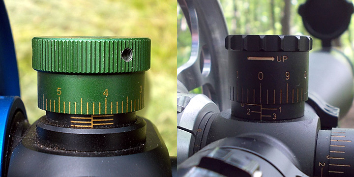
4. Establishing the Trajectory 4.1. Choosing Zero Distance 'Zero', in Field Target, is a bit of a misnomer. Unlike hunters, who utilise a fixed zero and use holdover/under for height corrections in order to save time, the majority of Field Target shooters will dial-in the correct elevation setting for every shot. The raised target- turrets that FT scopes possess also have a resettable calibration dial, usually marked in 1 minute-of-angle (MOA) large graduations, and smaller 1 MOA markings. This calibration dial will begin at zero. A zero, in Field Target, really amounts to this: The range, and position on the elevation turret from which all the other settings will be referenced. It's as simple as that. The choice is down to personal preference, although collective wisdom suggests zeroing at the zenith (top) of the trajectory, because all the elevation adjustments are upwards from zero, making things simpler. Or you can use a zero distance where you are still able to shoot one hole groups easily, so if you would just like to test your settings quickly, try your rifle on this distance. But in this case, the click values will be on both sides of the zero and this may be annoying. Of course, this goes out of the window when you put a piece of tape around the turret and mark the distances in yards directly on to the turret, without reference to MOA or numbers of clicks. In this case it can be said that your scope is zeroed for every range. It is for this very reason that a 'zero' in field target shooting is a bit of a misnomer. 4.2. Systems for Marking P/A Assembly and ElevationBefore you proceed to set up all the elevation settings on the range, it is important to decide on which system of marking the sidewheel/objective and elevation you are going to use. There are basically 3 ways to do it, with infinite variations thereof. I) Mark both the P/A and elevation turret in actual distance (Yardage) Just read distance from P/A, and then dial to that range. However, turret can become very cluttered as sub-zero ranges cross over and fight for space with major ranges. When this method is used there is no 'Zero' as such. When the numbers are too close to one another, you can use a bigger diameter turret or mark every 2 or 5 yards only.
II) Mark P/A with distance, but use existing Turret Graduations and Reference Chart As above the Parallax Assembly is marked in yards but, using zero as base reference, each elevation setting is recorded as being a certain MOA number, of amount of clicks, from zero. Unless you have a very good memory, the use of a 'click-chart' linking distance to MOA/clicks is essential. This method is not so comfortable, but you can use different pellet types easily, using each sort of pellet with its own chart.
III) Marking the P/A with the Elevation MOA numbers This system is a combination of the above two methods. It enables you to do away with a click-chart for day-to-day use, although a reference has to be kept somewhere. Rangefind, then dial in the correct MOA read from the P/A. This system removes an element of psychology from shooting at distance, and has the added benefit of preventing opponents from 'cribbing' your rangefinding readings.
Marking the P/A and elevation turret has an almost infinite number of variations. You can use letters instead of numbers, or use colours for 5-yard bands, without any writing whatsoever. You can even use measuring systems other than yards. Metric measurements are becoming increasingly popular and it is not unheard of to use purely arbitrary measurements like your own paces. Unorthodox, but it works for some. 4.3. Zenith of the Trajectory and Use of a Bottoming TurretThe first step in establishing the trajectory of a rifle/scope combination is to determine the Zenith, or high spot in the pellet's arc of flight. For rifles with muzzle energy of 11-12 ftlbs, with standard high scope mounts, this usually falls between 20 and 30 yards. To determine this high spot, place targets at 2.5-yard intervals between 20 and 30 yards. As before, the targets need only consist of a plain sheet of paper with a horizontal black line drawn across it. Shoot at the 25-yard target, adjusting the elevation until all your shots fall on the black line. Next, without altering the elevation setting from 25 yards, shoot at the black line on each of the 20, 22.5, 27.5, and 30 yard targets in turn. Whichever of these ranges has the highest groups of shots in relation to the line is the zenith of the trajectory. If you are going to install a bottoming turret, now is the time to do it. What is a bottoming turret? It is a custom-made oversize target-turret that sits snug on the scope body when the elevation is dialled to its minimum setting, i.e.: when set for the zenith of the trajectory. It actually serves two purposes. Firstly, because it is larger than the existing target-turret, any numbers that are written on it can be made larger, with more spacing between numbers. Secondly, certain scopes have 1/8 MOA click adjustments instead of 1/4 MOA. In some cases this means that the total range of adjustment between 8 and 55 yards is greater than one full revolution of the elevation turret. On a scope that has 6 revolutions of elevation adjustment available, it is vital that the scope is dialling within the correct revolution. Missing a target because, 'I'm a full-turn out!' is one of the most soul-destroying things that can happen in Field Target.
The bottoming turret prevents this by dogging down onto the scope body when the scope is set at the trajectory's zenith, so that the turret will not turn any further clockwise than that point. Also the normal turrets can be simply converted into a bottoming one using an O-ring with appropriate thickness on the neck of the turret. Any time the shooter thinks he might be a turn out he can simply dial back until the turret stops, and the correct turn is found.
4.4. Completing the Remainder of the Trajectory Firstly, ensure that your rifle contains enough air. This is particularly important for unregulated pneumatic rifles, because unless the elevations are set within the 'heart-of- the-fill' the settings will be incorrect. This will manifest itself as a wandering zero. Regulated pneumatics can also be affected, as the rifle comes 'off-the-reg' at the end of the air charge and may exhibit a sharp rise, followed by a sharp fall, in muzzle velocity and point-of-impact. Confirm over a chronograph that the rifle is doing the correct muzzle velocity. The way you now proceed depends entirely on your choice of 'zero'. If you wish to reset the elevation turret's calibration dial to, for instance, 35 yards, then that is the first distance you should 'shoot-in' and set. Obviously, if using a bottoming turret you will have to set the zenith-range first so that the turret can be locked down. By now you should have decided on which scope marking method to use. You will need access to a 55-yard (50 metre) range. Using either a 50-metre tape measure or previously measured markers, place zeroing boards at 5-yard intervals from 20 yards out to 55 yards. Ignore anything below 20 yards for the time being because they are of relatively minor significance and can be done in a separate session using the boards currently in use. As mentioned earlier, use plain paper or card, with horizontal lines drawn across. The lines are best done to about a pellet's width, with a permanent marker. You do not need any vertical aim points because when setting a gun/scope for elevation, it is best to completely divorce the left-to-right aiming component and concentrate on just holding the horizontal crosshair on one of the horizontal lines.
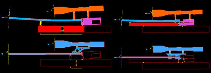
Starting at your chosen zero distance, shoot at a horizontal line, walking-in the shots by adjusting the elevation turret, until successive shots all land on the chosen line. Either mark the distance in yards onto the turret, or set the calibration dial to zero. To do this, loosen the set-screws (usually 1,2, or 3 hex-head screws) and rotate the dial until zero on the dial is lined up with the reference pointer. The reference pointer can be a triangular piece of white tape stuck on the scope body and pointing to the base of the turret. Re-tighten the set-screws. Now that 'zero' is established, move 5 yards further out. As before, shoot at a horizontal line and adjust elevation until the rifle is shooting on-line for that distance. Mark that distance onto the turret or count the number of clicks/MOA numbers, from zero. Proceed in this way until you have a setting for every 5-yard increment between 20 yards and 55 yards, whether it is a turret marked in yards, or a list of clicks/MOA. Each time you calibrate a different distance setting, make sure you adjust the objective / sidewheel until both the crosshairs and target are sharply in focus, in order to eliminate parallax error. It is possible, and indeed common practice, to calibrate the P/A for rangefinding at the same time as the elevation turret, but for the sake of simplicity it will be dealt with separately. Once the major ranges (20-55 yards) are complete, you can now do the ranges from 20 yards to 8. Targets are seldom placed closer than 20 yards, so it depends on how thorough you wish to be. 1-yard increments between 8 and 15 yards, and a setting at 17.5 yards are sufficient. Depending on the height of the scope above the barrel, the 8-yard setting could be a full revolution of the elevation turret up from the zenith-range. It might appear strange at first that the closer ranges are the one that require the most dialling. This will be explained in chapter 6. After all the minor ranges are shot in, double check each and everyone of the settings you've made, because differences in gun hold can set in throughout a zeroing session, especially in the inexperienced. Also check the gun over a chronograph before, during, and after a session. Double-checking the elevation settings also checks that the turret is tracking back to zero, as some scopes come with inferior turrets that stick in position. It's worth using a zeroing rest. Even if you shoot from the normal shooting position, you can easily check after a few shots, how much to adjust on the elevation, instead of trial-and-error every time. And you can try various ballistic software, like 'Chairgun'. It will be sufficient to zero your rifle on 10, 35 and 55 yards and use the other distances from the software. You can learn a lot of things about ballistics using this software, but maybe it's safer for a beginner to set everything with actual shots. Once you are happy that you have established the full trajectory, from 8-55 yards, it is time to set up the parallax adjustment for rangefinding. 4.5. POI-ShiftThe point-of-impact can move with temperature changes. The main reason of this is the different heat expansion of certain rifle/scope parts, but also the pressure changes in a built-in air cylinder can move POI. The trajectory of the pellet changes with the environmental conditions, too (the shots go higher in warm and damp air) but this is not significant. Most rifles change their muzzle velocity with temperature, you should check and reset it from time to time - or you have to know how much is it and deal with it while shooting. Basically, we have two alternatives to handle POI-shifts. We can (try to) eliminate them, or learn them by experience and make some corrections with scope settings. The main method of eliminating these problems is to make your barrel free floating, with a massive support on a 5-10 cm length and connect the scope mounts only on the same support. This ensures that the barrel and scope can move only together, see the illustrations below. Unfortunately, the scope can have some inside movements as well, which can not be corrected within our possibilities.
Without mechanical modifications there is only one chance left, zeroing the rifle at different temperatures (it has to be there at least half an hour before shooting) and based on these experiences, you will know if it is 10 degrees warmer or colder, how much compensation you have to do while aiming. It is worth learning your rifle's behavior at different temperatures because if you have enough real-world experience it does not count whether POI-shift is caused by the projectile velocity, the deformation of the rifle or the scope, simply you will know what to expect in different conditions. 5. Rangefinding by Parallax Correction 5.1. What is Parallax? Parallax is the apparent movement of the target relative to the reticle when moving your head up and down, while looking through the eyepiece of the scope. It occurs when the target does not fall on the same plane as the reticle. To eliminate parallax, certain scopes have an adjustable objective lens or side-focus dial. The shooter adjusts the front or side mechanism whilst looking at both the reticle and the target. When both the reticle and target are in sharp focus, with the scope set on its highest magnification, the scope is said to be free of parallax. That is the definition of parallax from a firearms point of view, where most shooting is done over 100 yards and the depth-of-field is deep. Airgun shooting is a rather different affair. When using a riflescope of substantial magnification at relatively close range (under 75 yards), the scope image will be out of focus (blurred) at any range other than that which it is currently set. This means that to have a usable sight picture, the objective or side focus has to be adjusted for each different distance you wish to shoot. Some years ago it was discovered that a side-effect of the parallax correction / focussing issue was that if a scope of sufficient (over 24x) magnification was used at typical airgun ranges, the shallow depth-of-field made it possible to calibrate the scope to accurately estimate distance. By marking the parallax adjustment with the distances at which the scope came into focus, what had been a simple parallax correction device had now become, for Field Target at least, a rudimentary, but very accurate, rangefinder. 5.2. Types of Parallax AdjustmentThere are 3 types: Front (objective), Side, and Rear. The rear-focus type is adjusted by means of a ring similar in size and location to the zoom ring. Rear focus scopes are rare and to date none have found their way into field target usage so they will not be dealt with further. That leaves front-focus, and side-focus. I) Adjustable objective (front focus) These are relatively simple mechanically and are generally less expensive than side-focus models. There are expensive exceptions, such as Leupold, Burris, Bausch&Lomb, and these models are popular in Field Target due to their exceptional optical quality. There is an ergonomic disadvantage to using a front-parallax scope however, and that is because of having to reach to the front of the scope to adjust it whilst looking through the scope. This is a particular problem in the standing and kneeling positions. Certain models, such as the Burris Signature, have a resettable calibration ring. Leupold scopes have a set-up where most of the front assembly does not rotate; the lens alone moves as you turn the knurled ring. With most front-focus scopes the entire front lens housing rotates. This can be very difficult to rotate smoothly and is a consequence of rangefinding being a secondary effect in scope terms, because scopes were not designed with focal rangefinding in mind. Hence this is a simpler structure which doesn't contain too many optical elements, therefore the chance of possible errors and faults is very low. There are different tricks to make the reading of ranges easier, like some collars around the objective or a prism to view the numbers from the shooting position. A left-handed shooter may find this type of scope more comfortable than a scope with a sidewheel.
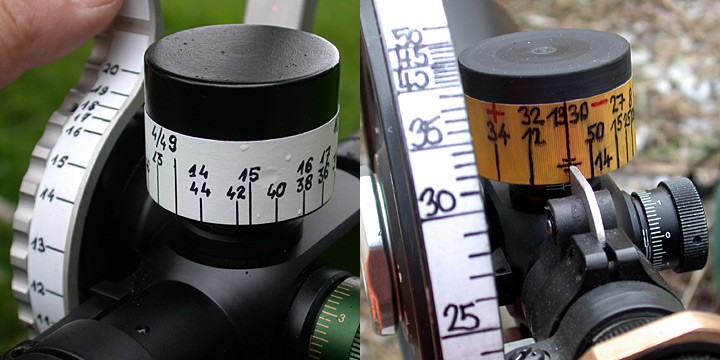
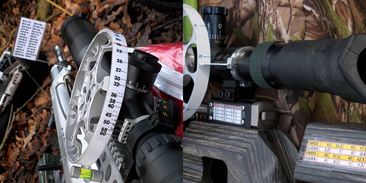
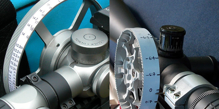
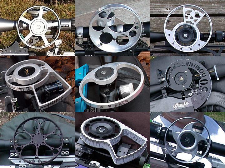
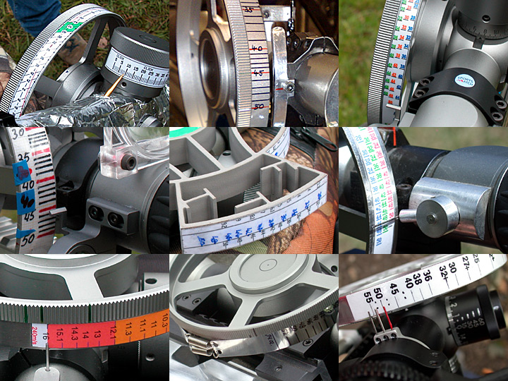
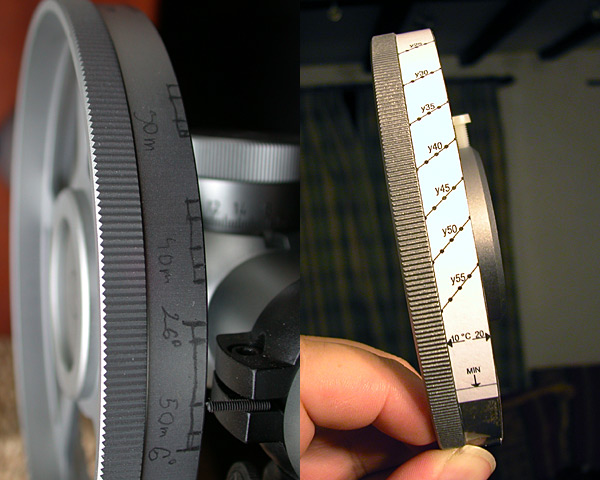
II) Side-focus parallax (Sidewheel) Side-wheel scopes are now mostly the norm, rather than the exception, in field target. Although generally expensive and limited in choice, they offer one major advantage over front-parallax models: The ease of reaching for the side-wheel instead of the front of the scope. The range markings on the wheel can be read without 'breaking stance', i.e: coming out of position. Side wheels are generally easier to rotate than objective lens assemblies therefore more sensitive adjustment is usually possible. This mechanism is much more vulnerable, though. If the wheel becomes loose, you will always have to dial the same direction before reading to eliminate the clearance. Side-wheel scopes are usually only supplied with a small focus knob, which is too small to cater for the 1-yard and 5-yard increments required in field target. This small wheel betrays its intended purpose as a parallax correction device rather than a rangefinder. Instead, a larger wheel is installed over the existing knob. The larger wheel is typically a machined disc of aluminium, which locks in place with grub screws or a collar system. The original knobs are usually 20-30 mm in diameter. Aftermarket wheels generally vary in size from 3-6 inches in diameter. It may also be necessary to fabricate a pointer for the wheel to replace the original item. A thin piece of plastic or metal wedged between the upper and lower scope mounts, extending to the edge of the wheel should suffice.
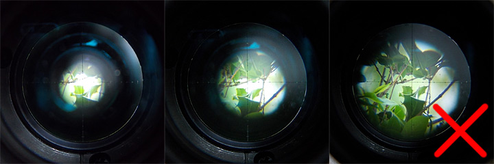
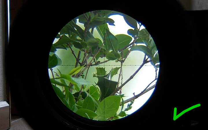
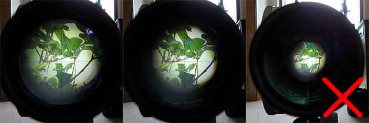
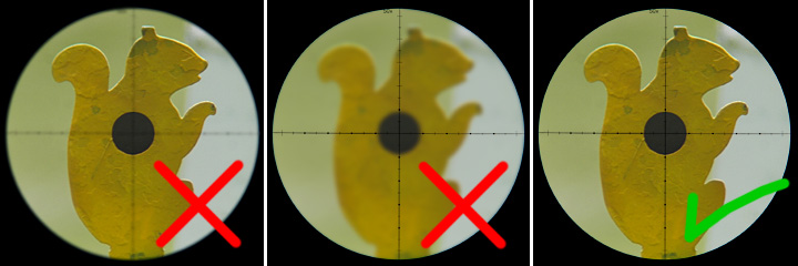
You can see some really huge wheels around the world but it's not worth having a bigger wheel than 6-7 inches, it's more vulnerable and the resolution will not improve, you will have bigger gaps but the errors will be bigger, too. It's advisable to fix the reading mark on the scope itself (e.g. with a third mount ring, or using a scope pointer), instead of tightening something between the two parts of the scope mount. This way you don't have to calibrate your parallax again if you have to remove your scope for some reason. 5.3. Calibrating the P/A for RangefindingThis is the hardest part of the entire setting-up procedure. Fatigue and frustration can set in during an extended session and eyestrain can result in a lot of wasted time and effort. During a FT competition, everything you do as part of the shot process will be a waste if you do not get the range-to-target correct, so it pays dividends to take plenty of time during P/A calibration. You will need access to a 50-metre range, tape measure, and targets. It is especially important that you use the correct type of target to set up your range markings. Standard knockdown field-targets are best, because they will be your only source of estimating range in a FT competition. Obtain two field-targets and spray one of them black with a white kill-zone. Spray the other white with a black kill-zone. Place the targets a safe distance away and shoot roughly ten pellets at each. This is to provide a contrast between the paint and the grey metal underneath. Taking some nylon reset cord, tie some large knots through the metal ring on the target faceplates. Again, the individual loops and windings in the string can be an invaluable aid to resolving a sharp focus of the image. It may be necessary to wrap a piece of tape around the circumference of the P/A assembly, to provide a surface on which to write your numbers. Fine-tipped permanent markers are best for writing on your tape. Alternatively, 'Letraset' rub-on numbers can be used directly on polished aluminium. Now is the time to decide which P/A marking method is to be used (see chapter 4.2). It is an unfortunate fact that as the range increases, the parallax differential (distance between markings) diminishes, merging to infinity pretty much after 75 yards. On average, the distance between 20 and 25 yards on a 5-inch sidewheel is about 25mm. Between 50 and 55 yards this falls to about 5mm. Consequently, the longer ranges are the most difficult to resolve accurately and repeatably. 20 yards is a good place to start. It is above the lower focus limit of the scope but is not so distant as to be difficult. Place both targets exactly 20 yards away from the front lens of the scope.. It is important that the front lens is used as the datum for all your measurements otherwise it may result in inaccurate range readings. Perform the following procedure: 1. Focus your eyes primarily on the reticle of the scope. Rotate the P/A until the black target is roughly in focus. As stated earlier, it is important not to try too hard. As you concentrate on the target, your own eyes will try to compensate for the parallax error and will bring the target in to focus while taking the crosshair out of focus (fig.1). You will not notice this until you stop looking at the target, at which point you will notice that the crosshair is sharp and the target has suddenly blurred out of focus (fig.2). That is why you should focus your eyes primarily on the crosshair/reticle and just take small glances at the target image, or, just use your peripheral vision to observe the target, while maintaining primary focus on the crosshair. That way, the target will 'snap-in' while the reticle stays sharp (fig.3).
With the 20-yard setting completed, move 5 yards further. Repeat the procedure for every 5-yard increment between 20 and 55 yards, constantly referring back to the other ranges to make sure nothing has changed. If things start to change, take a break and try again later. Once 20-50 yards have been completed, establish the shorter ranges to the precision you choose. As stated earlier, a setting for 17.5 yards between 15 and 20, followed by 1-yard steps down from 15 yards should prove more than sufficient. When you get near the close focus limit of your scope, measure that exact distance with the tape. You may have to move the target by as little as six inches at a time to determine this distance. It may turn out to be 8 1 yards or something like. Most of the scopes used in FT can not rangefind from 8 yards, but only from 10 or 15 yds. If you turn the magnification down, you'll see these close targets more sharply but never really sharply. A 'close focus adapter' can help this problem, but many shooters can live with it anyway. Whatever the distance, establish a turret setting for this range by shooting at one of the lined boards from earlier. You now have a scope that will rangefind for all the distances between each extremity of the rifles plotted trajectory.
Now for a test. This will require a friend or fellow club member. Ask them to put out several targets at different ranges, each having been measured with the tape. They will need to write these ranges down. Then, rangefind each of the targets in turn, calling out the range of each to your colleague. The person will write these next to the measured ranges. It is an interesting exercise because it tests your range readings in a realistic way. On a measured range your brain can fool you into turning the P/A by a certain amount because you know how far the target is. The test mimics match conditions because you have absolutely no way of knowing for sure the distance to the target, other than your scope. There is a saying in Field Target that is very true: Trust Your Scope. * * * * * * * * * * * * * * * * * * * * * * * * * If you have followed this manual this far, you will have set up your rifle and scope to a standard capable of winning any competition. The rest, as they say, is up to you. Welcome to the sport of Field Target. Enjoy yourself! 5.4. Parallax ShiftParallax shift is a well-known phenomenon, more or less each and every scope do suffer from it. The main reason is the change in temperature, but even the altitude above sea level or some photo filters can affect it. If we would like to compare different scopes' behavior related to rangefinding errors, it's always advised to use the rangefinding error of a 55 yards target by 10 degrees temperature difference. This value has been between 0.5-4 yards on the scopes which I have tested. There are several different ways to deal with parallax shift, from the appropriate shifting of the scale through multiple scales and slanted distance marks to multiple or adjustable pointers. But the point is that you have to learn your scope and its rangefinding on different temperatures.
Sadly, there is only one method to find out the corrections needed: you have to sit out in different seasons and times of the day, put out targets to every 5 yards and rangefind them many times very precisely. It is important that the scope remains in shadow and spends at least half an hour outside before starting.
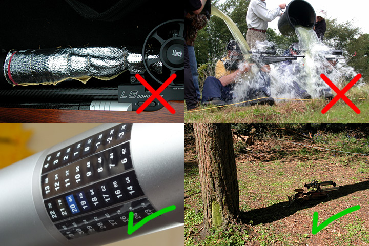
After a dozen experiments you will see how your scope reacts to temperature. Parallax shift can be continuous with temperature changes but can be almost none and then suddenly 'jump'. The switching temperature is not necessarily the same when jumping up or back but you can learn it after a while. If you already know how your scope works, you will also know how much and how to compensate in order to have correct rangefinding results. Insulating the scope is quite useless because this can protect it only from the direct sunlight but it still reaches the environmental temeprature in an hour and the parallax shift happens. Also, water cooling is not a good idea :-) We can do two things which are really useful: monitoring the temperature of the environment or it is even better if the scope itself (see picture below). And of course keep the scope in the shade all the time. Shooting is only 2-3 minutes so the scope can not get too much warmer and it has 10-15 minutes to get back to the air temperature.
6. Ballistics Explained 6.1. Why .177? As soon as an airgun pellet exits the muzzle, the pellet becomes subject to gravity and starts its fall towards the Earth. This is basic physics. Many people believe that a .177 calibre rifle has a less curved trajectory than .22. This is a somewhat misleading oversimplification. At 12ftlb muzzle energy, the average .22 pellet will have a velocity at the muzzle (MV) of about 600 feet per second (fps). Because muzzle energy is linked to pellet weight and .177 pellets are lighter than .22, the statutory 12ftlb limit enables a .177 rifle to operate at about 800 fps. In other words, when operating at the legal limit, a .177 rifle/pellet has a third as much extra velocity than .22. It all boils down to what the law allows. If the limit was on velocity, the two trajectories would be relatively similar to each other. But, for equal muzzle energy, the trajectory is somewhat less curved in .177 calibre:
The graph shows what happens when either calibre is fired with the barrel parallel to the ground. The .177 drops nine inches less than the .22 over 55 yards. This means that the shooter does not have to adjust the sighting system as much. A result of this is that .177 is more forgiving of errors in range estimation. 6.2. Observed Trajectory with Scope FittedIn the previous example, there was no sighting system. The measured drop points were referenced from the centre line of the rifle's bore (bore line). When you install a telescopic sight your sight plane is some distance above the rifle's barrel. This is the line-of-sight (LOS). As mentioned earlier, when a rifle is fired, the pellet starts shedding velocity immediately and gravity pulls it gradually towards the ground. If we want to accurately shoot at a target we need to elevate the muzzle in order to raise the Point-of- impact (POI). This is what happens when we mount a scope. You are looking straight at the target but the scope is set in such a way that the rifle is actually pointing upwards. Lets see what happens when we put a scope on to the .177 rifle in low mounts (scope centre 1.5 inches above bore centre, and zero it at the zenith of its trajectory (22 yards in this case):
The pellet exits the barrel 1.5 inches lower than the line of sight (LOS). The pellet is not initially rising, as is often believed. Instead, the LOS is pointing down relative to the pellet's flight path and will meet the trajectory at the chosen zero (in this case the zenith of the trajectory which is 22 yards), after which the pellet will begin to drop away from the LOS. It can also be said that the barrel is pointing up relative to the LOS. If you zeroed the rifle in the above example at 22 yards and shot at targets from 5 yards to 55 yards, measuring the actual distance between the point-of-aim and point-of-impact for each distance, the measurements obtained would produce the following chart:
In field target, holdover/under (aiming high or low) is seldom used, except when using a multi-aimpoint reticule. Instead, we adjust the elevation turret of the scope so that even though the rifle itself is actually being aimed high/low, the shooter is able to still aim dead-centre. The brain and eyes will instinctively try to aim using the centre of the crosshair, and so altering the scope to facilitate this enables a more accurate aim than trying to hold the crosshair on a point in space somewhere above the target. So, using the same gun/scope set-up as the previous example, zeroed at 22 yards, we adjust the scope for each distance, counting the number of clicks between each 5-yard increment. We then arrive at the following:
The first thing we notice about this graph is that it is a different shape to the previous chart for drop from zero (fig.4). In that chart there is a 0.5inch drop from zero for both 10 yards and 35 yards. But, instead of holding over by half an inch we adjust the elevation setting to 10 yards and yet it is not also the click setting for 35 yards. The 10-yard elevation setting equates to 45 yards, while the 10-yard holdover equates to 35 yards. Why is this the case? It is all due to minutes-of-angle. 6.3. Minute-of-Angle (MOA)There are 360 degrees in a circle. A degree is further divided into 60 minutes-of-angle (MOA). Most telescopic sights have adjustments measured in 1 MOA. This means that for one click, the scope is being adjusted by one quarter, of one sixtieth, of one degree. At 100 yards, 1 MOA describes a distance of 1.047 inches. This gets conveniently rounded down to 1 inch. 1/4 MOA equates to 1/4 inch, but only at 100 yards. As you go out past 100 yards each click describes a bigger distance than 1/4 inch while still remaining 1/4 MOA. As you come closer than 100 yards the opposite happens. Each 1/4 MOA adjustment becomes ever smaller than 1/4 inch the closer than 100 yards you come. At ten yards, each click moves the POI by only one fortieth (0.025) of an inch, yet it is still 1/4 MOA.
6.4. Increasing the Scope Height There are two reasons for increasing the scope height relative to the bore. The main reason is to allow a more vertical head position in order to relieve tension in the sitting position. The second reason is the beneficial effect on long-range trajectory. A shooter will increase the scope height primarily for the first reason and enjoy the trajectory benefits purely as a side-effect. In figure 3 we saw the trajectory of a .177 rifle operating at 790fps, with a scope set in low mounts, giving a scope-centre to bore-centre measurement of 1.5 inches. In the following diagram we see what happens when the scope is mounted in high mounts together with riser blocks, giving a scope height of 2.5 inches:
When the scope is introduced to the rifle, the LOS will converge with the trajectory at a later point than when the scope was set in low mounts, meaning that the zenith of the plotted trajectory will be 27 yards as opposed to the previous example of 22 yards. The drop from zero to 55 yards is reduced from -4.2 inches to -2.9 inches. However, when we plot the clicks required for this new trajectory we see the following:
The clicks from zero to 55 yards is reduced from 31 clicks to 21 clicks. All this changes when we look at the clicks from zero down to 8 yards. For the 1.5-inch scope height, all the required dialling is accomplished within just over half a revolution of turret travel. For the 2.5-inch scope height, 27-55 yards is accomplished within one third of a revolution. From 13 yards down to 8 yards takes a further two thirds of a revolution, making a total adjustment of one full revolution (60 clicks, or 15 MOA). There is no big advantage to be had in raising the scope height, other than the comfort issue. There is no detriment either, providing you can rangefind down to 8 yards and accomplish all the dialling within one turn of elevation. All that matters is that you know, and are comfortable with, your chosen trajectory. It's a common myth that the higher the mounts are, the more the canting error is, but this is not true. The shots from a canted rifle will impact along an arch, and the displacement of the pellet impacts depends only on the angle of the canting and the pellet drop at that distance (see Fig. 1 in chapter 6.1.). A detailed article about this question can be read here: The height of the scope has nothing to do with this. Why? It's proven by tests and can be proved theoretically, too - but now simply imagine a rifle with more scopes mounted on it, one above the other. Each scope is zeroed at the given distance, each sight line looks at the same point, where the gun will shoot. If you cant the gun with an angle, you might aim through any of the scopes, lower or higher, they look to the same point, the gun underneath will be in the same position too, so the canting error will be the same. The canted shots move along a circle and the amount of displacement depends only on the pellet drop (d) and on the angle of canting (a). It doesn't matter how high your scope is, you always have to pay the same attention to avoid canting the rifle.
6.5. Shooting uphill/downhill When you are shooting inclined, either uphill or downhill, the shots always go higher so you have to aim lower for a successful hit. 7. Trajectory Compensation by Holdover7.1. What is holdover? Holding-over is a method of trajectory compensation whereby, upon establishing a base zero, no further adjustments are made to the elevation turret from shot to shot when changing the target distance. Instead, all compensation is done by aiming high/low. This is done in one of two ways. The shooter can directly aim high by a specified amount, for example: holding the central crosshair level with the top of the killzone. This requires the shooter to have good spatial awareness and to know how small distances such as an inch relate to the killzone on a distant target. The second method is simply as refinement of the above. Instead of willingly putting the central cross somewhere above the target, the shooter will place some other part of the reticule in the centre of the target. The central cross will still be held somewhere other than the KZ, but the eye will be focussing within the crucial part of the target. This is usually facilitated by the use of a 'Mil-dot', or Multi-line reticule. 7.2. Multi-Aimpoint ReticulesThe standard duplex (thick-to-thin post) reticule, while perfectly acceptable for hunting at short range, is found wanting when it comes to accurately compensating for trajectory. This is where a multi-aimpoint reticule comes in. A 'Mil-dot' reticule has, in addition to the thick/thin crosshairs, several dots spaced at intervals along the thin parts of the crosshairs. It is possible to use these to allow for pellet drop much more accurately than the standard duplex. A multi-line reticule goes a step further. Instead of dots on the vertical crosshair, there is not one, but several horizontal lines, (or Stadia). One of these lines is used for the base zero, with the lines below it used for distances further from zero, and the lines above used for the zenith of the trajectory (if not zeroed at zenith).
7.3. Zeroing when using holdover The first thing to consider is which distance you are going to use as primary zero, i.e: which distance coincides with the central cross. After that, it is simply a matter of shooting at zeroing boards from 8-55 yards, adjusting your aim for each range so that you know which part of the reticule you have to place in the centre of the target for any given range. When using holdover it is not as important to optically centre the scope as it is when 'dialling', but it is still beneficial. Instead of centering at 10 yards it is done at the distance that coincides with the primary zero, since your scope will never be moved from that setting unless to re-zero. Below is an example which shows how the dots in a mil-dot reticule can be used to give aim-points between 8 and 55 yards. It is not a precise example and is only given to illustrate the principle, because the placement of the points of impact within the reticule is completely dependent on the magnification selected. For this reason, shooters using holdover/multi-aimpoints tend to choose a magnification early on in their shooting careers and stick with it. (The numbers and small horizontal lines would not appear in the actual reticule):
|
|||||||||||||||||||||||||||||||||||||||||||||||||||||||||||||||||||||||||||||
![[br]](../bfta-manuals-updated/br.png "[br]") Brasiliero / Brasilian (by Delphinus)
Brasiliero / Brasilian (by Delphinus)![[de]](../bfta-manuals-updated/de.png "[de]") Deutsch / German (by Henning)
Deutsch / German (by Henning)![[ee]](../bfta-manuals-updated/ee.png "[ee]") Eesti / Estonian (by Kristin)
Eesti / Estonian (by Kristin)![[fr]](../bfta-manuals-updated/fr.png "[fr]") Français / French (by Robert)
Français / French (by Robert)![[pl]](../bfta-manuals-updated/pl.png "[pl]") Polski / Polish (by Chris)
Polski / Polish (by Chris)![[pt]](../bfta-manuals-updated/pt.png "[pt]") Português / Portuguese (by Delphinus)
Português / Portuguese (by Delphinus)![[si]](../bfta-manuals-updated/si.png "[si]") Slovenski / Slovenian (by Dušan)
Slovenski / Slovenian (by Dušan)![[tr]](../bfta-manuals-updated/tr.png "[tr]") Türk / Turkish (by BsR)
Türk / Turkish (by BsR)